Email Us :contact@ionic.co.in

An ISO 9001:2015 Certified company

- Primary & Secondary Clarifiers
- Oil Water Separation System
- Conventional Activated Sludge Process
- Moving Bed Bio Reactor (MBBR)
- Sequential Batch Reactor (SBR)
- Membrane Bio Reactor (MBR)
- Upflow Fluidised Bed Anerobic Bio Reactor
- Sludge Dewatering System
Primary & Secondary Clarifiers
Is Required when high suspended solids removal is needed
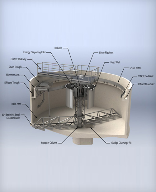 Ionic supplier circular clarifiers for treating raw water, raw sewage and industrial waste water to remove suspended solids, biomass etc. Various sizes and optional equipment for chemical dosing are available.
- Fly Ash Waste
- Flue Gas Desulfurization (FGD) Waste
- Clarification
- Solids Recovery
- Cooling Tower Blow down
- Iron Removal
- Municipal Water Treatment
- Semiconductor Process Waste
- Whitewater (Pulp & Paper)
- Groundwater Remediation
- Potable Water Clarification
- Landfill Leachate
- Boiler Waste Treatment
- Heavy Metals Removal
- Filter Press Belt Wash
- Battery Plant Heavy Metals Removal
- Hazardous Waste Remediation
- Brine Clarification
- Plating and Finishing Wastes
- Food & Beverage Waste
- Trace Metals Reduction
- Storm Water Management
- Bleach Plant Wash Water
- Incinerator Wet Scrubber
- Potable Water Pretreatment
Oil Water Separation System
Is required when reliable oil & grease, hydrocarbons including diesel, petro, kerosene from water is to be removed completely below detectable level
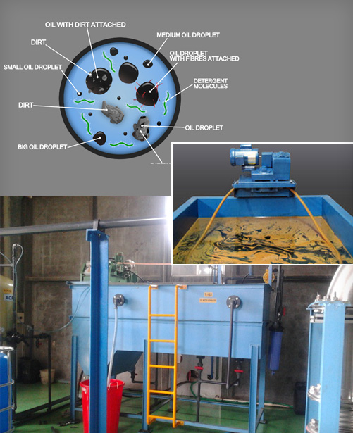 Oil& Grease removal is a tough task that too when oil is mixed with suspended particles and mixed with water. Oil can be free floating form or in emulsified form. IONIC has the technology to remove all types of oil and hydrocarbons from water reliably and completely well below the discharge norms.
OIL SKIMMER
IONIC can offer various types of floating oil skimmer including floating skimmer, belt type, tube type and disc type to suit various working conditions.
A tube type oil skimmer is provided in the collection tank to skim the floating oil from the surface which will be collected in a drum
Deemulsification and flocculation
As you will see from the above picture the nature of oily waste water is complex. Oil can be free or emulsified or attached to dirt etc. For effective separation, dirt has to be separated from oil as much as possible. Oily emulsion if present needs to be demulsified with specialty chemical so that it can easily float and comes to the surface in the oil water separator.
A dosing pump is provided for dosing the deemulsifier accurately. Dosing will happen automatically whenever the transfer pump pumps the waste water in to the oil water separator.
Oil water separator
Oil water separator is an state of the art technology used to separate emulsified oil from effluent. The device is filled with PP parallel plate media which is hydrophobic and oleophilic. It attracts oil droplets to make them accumulate on the plate surface. The V wing shaped plates are inclined at an appropriate angle to provide the solids and oil separation. When the oily waste water passes through the OWS separator plate packs in cross flow the oil droplets rises to the top and the solids settles down on the plates. The separated oil rises to the top of the surface from which it is skimmed using a pipe skimmer whereas the settled solids slide to the zone of zero turbulence and gets collected in the hopper bottom of the OWS. The settled solids are periodically drained through a paper ban filter.
The heart of the system is the special oil coalescing parallel plate pack which does not allow any clogging to happen on the media and provides large surface coalescing area and low turbulence and laminar flow to ensure most of the oil droplets are removed.
Conventional Activated Sludge Process
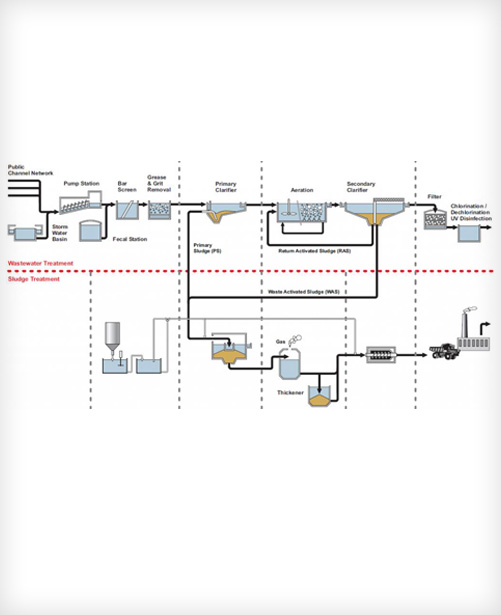 This system consists of primary Clarifier, Aeration tank and Secondary clarifier to remove biomass. Fine bubble diffused aeration system is implemented for effective aeration of the biomass and to increase the Oxygen transfer efficiency and reduce operating cost. Optionally tertiary treatment system is provided to remove residual BOD, Suspended solids and turbidity and the final treated water is disinfected with Chlorine Dioxide.
Moving Bed Bio Reactor (MBBR)
Is required when pre-engineered packaged sewage treatment plant is needed
 The moving bed bio reactor uses a special bio media on which bacteria is attached which degrades the organic pollutants present in the sewage and industrial waste water. The advantages of MBBR technology includes less space requirement, simpler operation, ease process control, flexibility to upgrade and increase the capacity by adding more media which is described in the following sections.
The MBBRTM biofilm technology has been used for about 20 years for greenfield wastewater treatment plants as well as supplementing old ones. The technology may be used for industrial as well as municipal wastewaters.
The Moving Bed biofilm reactor is a patented process based on MBBR biofilm technology. It utilizes the advantages of activated sludge and previous biofilm systems without being restrained by their disadvantages. The basic idea behind MBBR is to have a continuously operating, non-cloggable biofilm reactor with no need for backwashing, low head loss and high specific biofilm surface area. This is achieved by growing biofilm on small carrier elements (Picture 1) that move along with water in the reactor. The movement is caused by the aeration in the reactor. The carrier element is made of polyethylene or polypropylene with a density of slightly less than water and shaped like small cylinders about 9-64 mm in diameter, depending on the application. The filling rate of carriers in the reactor may vary between 10 and 65 %, also depending on the application.
The microorganisms grow on the carriers as a biofilm, see Picture 2. In the biofilm, the microorganisms are well protected which makes the process tolerant towards variations and disturbances and even extreme loads can be handled. With the MBBRTM biofilm technology, the process can be made very compact, since the microorganisms in the biofilm are very efficient. The process is also easy to maintain and the amount of active biomass is self regulated and depends on incoming load and hydraulic retention time. Since the carriers are continuously moving, the process is insensitive to suspended solids in influent wastewater.
The oxygen needed by the microorganisms in the process is supplied through an aeration grid covering the bottom of the reactor, see Picture 3. The aeration is at the same time keeping the reactor content completely mixed.
In order to retain the carrier elements in the reactor, a sieve is placed at the outlet of the reactor, Picture 4. The air agitation is arranged so that the carrier elements are constantly being moved upward over the surface of the sieve.This creates a scrubbing action that prevents clogging. Both the aeration system and the sieves are designed to work well with the chosen carrier elements.
The produced excess sludge sloughs of the carrier media, bypasses the outlet sieves and passes to the post-treatment step for further treatment and ultimate removal.
ADVANTAGES OF MBBR TECHNOLOGY
COMPACT
- Smaller Foot Prints
- Low Investment Cost
ROBUSTNESS AND OPERATIONAL RELIABILTY
- Stable under large load variations
- Tolerant to disturbances
- Recovery very quickly after major upsets
- No Clogging of reactors
- No risk of Sludge Bulking
FLEXIBILITY
- Almost all shape of reactor can be utilized
- Possibility to utilize existing tanks for Bioreactors
- East to expand in future
- Can be upgraded from initial design – add more media
SELF CONTROLLING BIOMASS
- No F/M ratio , SVI, Sludge Wasting Rates
- No MLSS to be maintained
NO SLUDGE RETURN LOOP
Sequential Batch Reactor (SBR)
Underground desgin - Is required when automatic simple, flexible, reliable performance is needed
IONIC offers packaged prefabricated underground Sewage Treatment systems with SBR (Sequential Bioreactor) technology in a compact form factor. They are very compact with limited civil work, offer value for your money and "peace of Mind". Using biological process they reduce organics pollutant by > 90% and makes the treated water safe for recycling for various purposes like gardening or disposal. Various standard configurations available 7 KLD-75 KLD available ( 4 PE – 1500 PE)
Every single person uses an average of 130-150 litres of water per day – water which then needs to be treated after use. For factories we can consider between 35-50 lpd. IONIC's small wastewater systems bring domestic wastewater back into nature without posing any kind of risk and therefore harmonizing the natural cycle.
We achieve this aim by means of the SBR method. SBR stands for: Sequencing Batch Reactor
Loading phase
The wastewater is initially fed into the sludge tank (1st chamber) where solid constituents are removed. From here, the wastewater is then gradually led into the SBR tank (2nd chamber).
Aeration phase
The SBR tank is where the actual biological treatment process takes place. Here, short aeration and rest phases alternate with one another within the scope of a controlled cleaning process. This means that the so-called activated sludge with its millions of micro-organisms can develop and treat the water thoroughly.
Rest phase
During the 90-minute rest phase, the activated sludge then settles on the bottom of the tank. A clear water zone forms in the upper part of the SBR tank.
Clearwater extraction
The separated clear water is then led from the SBR tank to the receiving water (Treated water tank, public sewer stream, river or lake) or into a percolation system. Afterwards, the sludge is returned to the first chamber from the SBR tank and the process starts again from the beginning. The treated water quality achievable is specified below for your ready reference.
OPERATION:- WITH WEB BASED REMOTE CONTROL, MONITORING AND TROUBLE SHOOTING
Operation and maintenance of sewage treatment is a messy and costly process. For proper operation skilled man power is necessary which is scarce and if it is available it is costly. IONIC has understood the necessity for having proper and easy operation.
The Web Monitor® takes over the legally stipulated daily controls and automatically saves the plant data once a month. This means that the operator is relieved of its monitoring duties. The Web Monitor performs this task on the operator's behalf by calling the plant on a daily basis to check its operational status.
In the event of errors in the plant the Web Monitor® sends an error notification to the address stored in the system by SMS or Email.
The operator can then act upon this immediately in the plant. Errors can be acknowledged and settings can be changed. Travelling time and costs no longer apply and the operator receives direct and fast assistance. All events are automatically saved in the Web Monitor® and made available to download.
SLUDGE HANDLING
The sludge is allowed to accumulate in the collection and equalization tank and dispose the sludge periodically every 4- 6 months interval through a Municipal disposal agency.
Why you should select KLARO Sewage treatment system ?
- 98% cleaning performance in just 6 hours (four cycles per day)
- Variety of sizes to select from 4 PE to 2000+ PE
- High treated effluent quality conforming the tolerance limits of pollution control boards
- A trusted product from a consultant specialist of IONIC
- Total biological treatment without using any chemicals
- Optional - Ultra-violet treatment or Chlorine Dioxide for disinfection
- Ability to install quickly because the equipment is prefabricated
- Container with range of materials; fiberglass, concrete and plastic
- Underground system that is invisible and saves space
- Safe to operate because there are no moving parts in the container (all the pumping operations of the system uses an air lifter)
- Energy saving with fine bubble aeration and holiday operation
- Optimum effluent treatment quality. The treatment process cycles in four significant phases.
- Energy saving – the air compressor works only for 10-12 hours a day thus significantly saving energy unlike other biological processes that needs to be aerated for 24 hours. Also the system controls detects under load condition and adjust the operation accordingly to save energy and safe guard biomass.
- Remote monitoring and Operation with GSM modem
Membrane Bio Reactor (MBR)
Is required when high quality treated water suitable for recycling needed in compact foot print
.jpg) IONIC can design and manufacture a range of IMBR (Immersed MBR) system using hollow fibre and plate and frame type membrane configuration. The Biological Oxidation in the Bioreactor is carried out by the Activated Sludge Extended Aeration process. The mixing condition within the chamber is intermediate plug flow between the conventional and totally mixed one. A high microorganism population is maintained within the Aeration chamber. A mixed liquor sludge concentration (MLSS) in the range of 7000-12000 mg/l is maintained within the chamber. However, for design purposes an average value of 8000 mg/l has been considered giving certain additional margin of operational flexibility particularly in the winter months.
IONIC can design and manufacture a range of IMBR (Immersed MBR) system using hollow fibre and plate and frame type membrane configuration. The Biological Oxidation in the Bioreactor is carried out by the Activated Sludge Extended Aeration process. The mixing condition within the chamber is intermediate plug flow between the conventional and totally mixed one. A high microorganism population is maintained within the Aeration chamber. A mixed liquor sludge concentration (MLSS) in the range of 7000-12000 mg/l is maintained within the chamber. However, for design purposes an average value of 8000 mg/l has been considered giving certain additional margin of operational flexibility particularly in the winter months.
The mixed effluent from the Aeration Chamber flows into a Membrane Bioreactor Tank (MBR Tank) fitted with Submerged Filtration Membranes where treated final effluent is separated from biological solids. The sludge collected within the MBR Tank is either recycled into the Anoxic Tank or part of it is wasted into the Sludge Holding Tank. The sludge from sludge holding tank is sent to Bucket Type Centrifuge for dewatering and drying. The Clear treated Sewage is collected by Permeate Pumps into a buffer cum chlorine contact tank for Final Disposal or recycle /reuse.
The other technologies work on just the concentration of microorganisms in the Aeration chamber, where as in MBR technology the treatment is based on concentration of microorganisms as well as membrane separation of the suspended particles. MBR technology is hybrid of conventional and membrane separation technologies. MBR based systems have higher concentration of microorganism which make it very efficient than other technologies.
The treated sewage from MBR plant shall be better than the required effluent standards of Pollution Control Board and suitable for recycle or reuse.
The typical MBR treated water quality is
Treated Sewage Effluent Parameters
- BOD - <5 Mg/l
- TSS - <5 Mg/l
- TKN-N - <5 Mg/l
- NH3 N - <1 Mg/l
- COD - <20* Mg/l
- Coliforms - <100 Per 100 ml
*Expected effluent quality assumes soluble fractions of COD are biodegradable to this level
Upflow Fluidised Bed Anerobic Bio Reactor
Upflow anaerobic sludge blanket (UASB) technology, normally referred to as UASB reactor, is a form of anaerobic digester that is used for wastewater treatment.
The UASB reactor is a methanogenic (methane-producing) digester that evolved from the anaerobic clarigester. A similar but variant technology to UASB is the expanded granular sludge bed (EGSB) digester.
UASB uses an anaerobic process whilst forming a blanket of granular sludge which suspends in the tank. Wastewater flows upwards through the blanket and is processed (degraded) by the anaerobic microorganisms. The upward flow combined with the settling action of gravity suspends the blanket with the aid of flocculants. The blanket begins to reach maturity at around three months. Small sludge granules begin to form whose surface area is covered in aggregations of bacteria. In the absence of any support matrix, the flow conditions create a selective environment in which only those microorganisms capable of attaching to each other survive and proliferate. Eventually the aggregates form into dense compact biofilms referred to as "granules".
Biogas with a high concentration of methane is produced as a by-product, and this may be captured and used as an energy source, to generate electricity for export and to cover its own running power. The technology needs constant monitoring when put into use to ensure that the sludge blanket is maintained, and not washed out (thereby losing the effect). The heat produced as a by-product of electricity generation can be reused to heat the digestion tanks.
The blanketing of the sludge enables a dual solid and hydraulic (liquid) retention time in the digesters. Solids requiring a high degree of digestion can remain in the reactors for periods up to 90 days.Sugars dissolved in the liquid waste stream can be converted into gas quickly in the liquid phase which can exit the system in less than a day.
UASB reactors are typically suited to dilute waste water streams (3% TSS with particle size >0.75mm).
Sludge Dewatering System
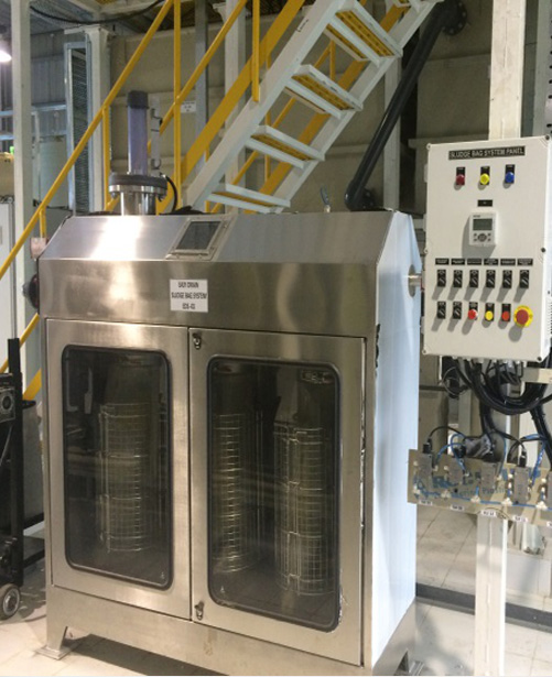 The automatic "EASY DRAIN" system dewaters and bags sludge from industrial effluent and domestic wastewater treatment plants. The system is capable of treating up to 100 kg D.S. of sludge a day.
This system is modular and is designed to optimise the filling and dewatering cycle of the filter bags. Once this cycle is over the full bags can be removed, sealed and stored in the open air for a further period of dehydration, reducing the weight and volume of the sludge cake. The special water repellent material of the sacks prevents rainwater from entering but allows dehydration of the contents by evaporation. The sacks are mounted on a special stainless steel frame, designed to distribute the sludge. The system is electronically controlled from a programmable control panel, ensuring correct process operation. Before dewatering the sludge should be conditioned with polyelectrolyte. After a few hours operation, dry solids content of 15 - 20% can be achieved, depending on the nature of the sludge. The volume of dewatered sludge is dependent on the solid content. For 1% dry solids, one machine can treat up to 20 m3 per day.
After the initial dewatering stage on the machine, the sacks are sealed and removed with a special sack trolley and stored in an open area (after 10-24 h). During the second phase, due to the special hydrophobic sack material, sludge weight and volume continue to reduce, regardless of weather conditions. After 2-3 months storage, a cake of 50-70% dry solids content is produced. As an example, 1500 kg of sludge at 1% solids content would give, after the first phase - weight of sludge 70-80 kg ( 20% dry solids), after two months, a cake of at least 50% dry solids content. This would weigh only 35 - 40 kg and represents almost a 50-fold reduction of the original weight.
FEATURES AND BENEFITS
Various models are available, with 2, 3, 6 and 12 sacks. Operation may be manual, with filtration taking place under gravity, or automatic with pressurized filtration. Multiple units may be installed, either in series or in parallel, to meet any requirements.
- Compactness and low space requirements
- An internal sludge distribution system with sack collars and clamps in stainless steel
- A drainage collection tray beneath the machine and sack positioned for easy handling
- Filtrate collection tank
- High efficiency, dewater to 50 - 70% D.S
- Low operating and maintenance costs
- Min. consumption of energy
- Very small area of installation
- Low costs of transport, sludge mass decreased up to 60 times
- Use of normal means of transport for sludge disposal
- Modular units - easy increase of capacity
- Simple to install, without special construction work
- Neatness and comfort in the all process
- Safe for environment
- Highly effective and reliable work throughout the year
- Total costs reduction of sludge disposal
Planning for a project ?
Get in touch with us.. We love to serve you..
Call : 020-27475272 / 8275486263 or Write to us
Copyright ©. Ionic. All Rights Reserved Login Sitemap Privacy Policy